
Once the PDU is added I will also need to link check power port to a device.
Example:
A Rack has 2 PDU’s (PDU-A and PDU-B) and lets say the PDU has 16x C13 power ports (1 – 16) and 4x C19 power ports (17 – 20).
Switch 1 PSU1 connects to PDU-A power port 1
Switch 1 PSU2 connects to PDU-B power port 1
and so on
- Noticed that most important is what you call “power port” vs. “power outlet”
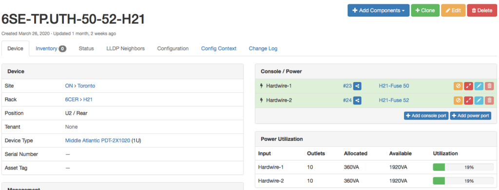
- if want to see power reserve calculations, your device must have have “Allocated draw” specified.
- For allocated draw of device refer to manufacture documentation.
- E.g. Cisco WS-C3650-48TD-L – average allocated draw is 90W Average Weighted
- (as per Cisco documentation page 33 of data sheet)
+-----------------------+
| Power panel 1 | name in Netbox: 6SE-TP.UTH
+-----------------------+
| |
| |
+---------------------+ +---------------------+
| Power feed 1 | | Power feed 2 | name in Netbox: Fuse 50, Fuse 51
+---------------------+ +---------------------+
| |
| |
| | <-- Power ports (2)Hardwire-2
+------------+ +-----------+
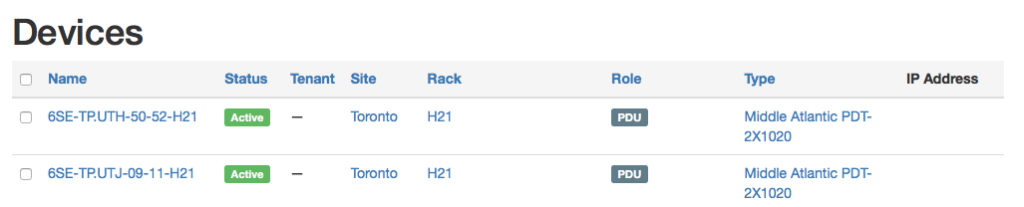
| PDU 1 | | PDU 2 | name in Netbox: 6SE-TP.UTH-50-52, 6SE-TP.UTH-09-11
+------------+ +-----------+
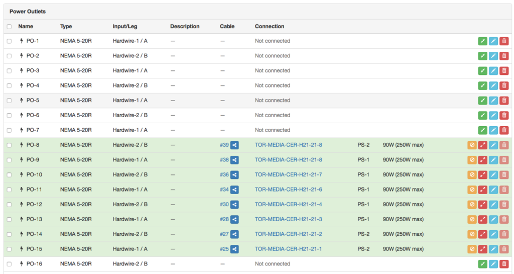
| \ / | <-- Power outlets (20) PO-1..16
| \ / |
| \ / |
| X |
| / \ |
| / \ |
| / \ | <-- Power ports PS-1
+----------+ +----------+
| Server | | Router | name in Netbox SWITCH-H21-21-1
+----------+ +----------+Distribution panels, fuse boxes are in Power menu.
PDU in the rack is represented as a device with 2 Power Ports and 20 Power Outlets
Device page has drop down menu “+ Add Components”. This is where you would create
your PDU based on what type of ports you have available to you

You can’t create cables under DCIM > Cables (except via CSV import), instead:
- go to one end, e.g. a power port
- click on the “Connect” button
- select “power outlet” or “power feed” as appropriate from the drop-down menu
- then you’ll get a page allowing you to select the other end and create a cable between them