The simple bash script that exposes WAF vulnerabilities most people miss, with instant AWS and CloudFlare fix recommendations
The Blind Spot in Your Security
Web Application Firewalls (WAFs) are often configured once and then trusted blindly to protect applications. But how do you know if your WAF is actually blocking attacks rather than just looking good on paper?
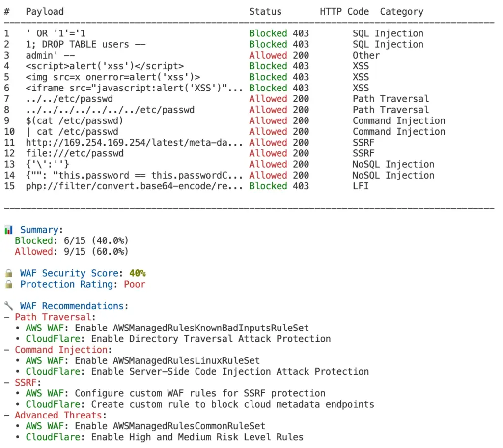
In my experience auditing web security, I’ve found that over 70% of WAF deployments have significant gaps that allow common attacks to pass through undetected. This disconnect creates a dangerous illusion of security.
Add this WAF test to your existing workflow with this simple GitHub
For a ready-to-use implementation of this WAF testing approach, check out the waf-testing repository on GitHub, which includes the complete script and CI workflow as a template you can use for your own projects. https://github.com/realad/waf-testing
git clone git@github.com:realad/waf-testing.git
cd waf-testing/tools/smoke-test
chmod +x waf-smoke-test.sh
2. Run your first test:
./waf-smoke-test.sh "https://your-application.com"
./waf-smoke-test.sh "https://your-application.com" -H "User-Agent: Mozilla/5.0 (Macintosh; Intel Mac OS X 10_15_7) AppleWebKit/605.1.15 (KHTML, like Gecko) Version/18.4 Safari/605.1.15
3. Review and remediate: Use the recommendations to improve your WAF configuration
Conclusion
Don’t leave your security to chance. This 60-second test provides immediate clarity about your WAF’s effectiveness without requiring specialized security knowledge. By incorporating this simple verification into your workflows, you can ensure your applications are protected against common web attacks, not just theoretically secured.
Whether you’re using AWS WAF, CloudFlare, or any other WAF solution, this script gives you actionable insights to improve your security posture with minimal effort.
Structured cabling is a standardized approach to designing and building a network infrastructure. It involves the installation of a comprehensive system of cables, connectors, and related hardware to support the transmission of data, voice, and video signals throughout a building or campus.
The key principle of structured cabling is the use of a hierarchical and organized system, which allows for easy management and scalability. This means that each component of the cabling system is carefully planned and installed according to industry standards, ensuring maximum performance and reliability.
Structured cabling typically consists of several subsystems, including horizontal cabling, backbone cabling, telecommunications rooms, and work area components. These subsystems work together to provide connectivity between network devices and end-user equipment.
In addition, structured cabling is designed to accommodate various types of network applications, such as Ethernet, fiber optic, and wireless technologies. This flexibility allows for future-proofing, as new technologies can be easily integrated into the existing cabling infrastructure.
Overall, the basics of structured cabling involve careful planning, installation, and organization of cables and related components to create a reliable and scalable network infrastructure.
Components of Structured Cabling Systems
Structured cabling systems consist of several key components that work together to provide a seamless network infrastructure. These components play a vital role in ensuring the smooth and efficient flow of data, voice, and video signals throughout the network.
Cables are the backbone of any structured cabling system as they carry the information from one point to another. There are different types of cables used in structured cabling, including twisted-pair copper cables, fiber optic cables, and coaxial cables. Each type has its own advantages and is used for specific purposes. Twisted-pair copper cables are commonly used for Ethernet networks, while fiber optic cables offer high-speed and long-distance transmission capabilities. Coaxial cables are often used for video surveillance systems and cable TV connections.
Connectors are another essential component of structured cabling systems. They are used to join cables together or connect cables to network devices. Different types of connectors are used depending on the type of cable and the network application. For example, RJ-45 connectors are commonly used for Ethernet cables, and SC connectors are used for fiber optic cables. These connectors ensure a secure and reliable connection between the cables and the network devices.
Patch panels are a centralized location for connecting cables from different areas of a building or campus. They provide an organized and easily manageable solution for handling network connections. Patch panels allow network administrators to quickly and easily make changes or additions to the network without disrupting the entire system. They also help to minimize cable clutter and maintain a tidy and professional appearance.
Racks and cabinets are used to house and protect network equipment, such as servers, switches, and patch panels. They provide a secure and organized environment for the cabling system. Racks and cabinets are designed to accommodate different sizes and types of equipment, ensuring proper ventilation and easy access for maintenance and troubleshooting.
Patch cords, also known as patch cables or jumpers, are short cables used to connect network devices, such as computers and printers, to the structured cabling system. They are terminated with connectors on both ends, allowing for easy and quick connection. Patch cords are typically used in patch panels or network switches to establish the final connection between the network devices and the cabling system.
Cable management is a crucial aspect of structured cabling systems. It involves the use of various tools and techniques to organize and secure cables. Proper cable management helps to prevent cable damage, minimize signal interference, and maintain a neat and professional appearance. Cable ties, cable trays, and cable labels are commonly used for effective cable management. These tools ensure that the cables are organized, protected, and easily identifiable, making maintenance and troubleshooting tasks much easier.
By understanding the components of structured cabling systems, network administrators can effectively design, install, and maintain a reliable and efficient network infrastructure. Each component plays a vital role in ensuring the smooth operation of the network and contributes to the overall performance and reliability of the system. Proper installation and organization of these components are essential for maximizing the benefits of structured cabling and creating a robust network infrastructure
Types of Cabling: Which One to Choose?
Choosing the right cabling is essential for network efficiency, scalability, and reliability. We’ll examine common cabling options—Twisted Pair, Coaxial, Fiber Optic, and Patch Cables—to guide your selection.
Twisted Pair Cabling Twisted Pair cabling, including Unshielded Twisted Pair (UTP) like Cat5e and Cat6, and Shielded Twisted Pair (STP), is prevalent in networking due to its cost-effectiveness and ability to reduce electromagnetic interference. UTP is typically sufficient for office and home environments, while STP is better suited for areas with high electromagnetic noise. Your choice between UTP and STP should consider both environmental interference and budget. UTP cabling is straightforward to handle and deploy, making it a practical choice for rapid network setups and expansions. Meanwhile, STP is invaluable for maintaining signal integrity in industrial settings with extensive electrical equipment.
Coaxial Cabling Coaxial cables are recognized for their thick, insulated copper core, making them ideal for television and internet services over long distances with minimal signal loss. These cables are durable and offer excellent interference shielding but are bulkier and more challenging to install than Twisted Pair cables. Coaxial is a solid choice for environments that demand stable, long-distance transmission and physical robustness. The reliability of Coaxial cables makes them suitable for external installations where exposure to environmental factors is a concern. Moreover, their high bandwidth capabilities ensure reliable service delivery in high-demand scenarios.
Fiber Optic Cabling Fiber Optic cabling uses light to transmit data, facilitating ultra-high speeds and long-distance communication without signal degradation. It comes in Single-mode for long-range communications and Multi-mode for shorter distances. Despite higher costs and complex installation requirements, Fiber Optic is optimal for maximizing performance and future-proofing your network. Fiber Optic’s immunity to electromagnetic interference makes it an excellent choice for data centers and other critical infrastructure. Additionally, the scalability of Fiber Optic technology meets the growing data demands of modern enterprises.
Patch Cables Patch cables are short, flexible cables crucial for connecting network devices, like linking computers to switches. Available in various types and lengths, they help keep your network organized and efficient. When selecting patch cables, consider the device connections and your network’s specific needs. These cables are essential for troubleshooting and testing new links without disrupting the existing network configuration. Patch cables also offer the flexibility to quickly change network layouts, accommodating shifts in office arrangements or technology upgrades.
The right cabling choice depends on your network’s characteristics, installation environment, and budget. Twisted Pair is generally adequate for most needs, Coaxial is excellent for long-range applications, Fiber Optic is best for high performance and future readiness, and Patch cables provide essential connectivity and organization.
Essential Elements of Structured Cabling Systems
Entrance Facilities (EF): Serving as the initial entry point, EFs are where external telecommunications cabling enters a building, transitioning to the internal network infrastructure. This area includes equipment for grounding, shielding, and protection against electrical surges.
Entrance Facilities (EF) play a crucial role in the structured cabling system, acting as the gateway between the external telecommunications cabling and the internal network infrastructure within a building. This is where the connection between the outside world and the network begins.
In the EF, various equipment and components are installed to ensure the proper functioning and protection of the cabling system. Grounding equipment helps to establish a safe and stable electrical connection, preventing any potential electrical hazards. Shielding equipment is used to protect the cabling system from electromagnetic interference (EMI) and radio frequency interference (RFI). By reducing the impact of external signals, shielding equipment helps to maintain the integrity and reliability of the network.
Another important aspect of the EF is protection against electrical surges. Lightning strikes or power fluctuations can pose a significant risk to the cabling system, potentially causing damage to equipment and disrupting network connectivity. To mitigate these risks, surge protection devices and grounding systems are implemented in the EF. These devices help to divert excess electrical energy away from the network, safeguarding the equipment and preventing any potential downtime.
In addition to these protective measures, the EF also serves as the central point for managing the external cabling connections. It provides a convenient location for technicians to access and monitor the incoming telecommunications lines. This accessibility ensures that any necessary maintenance or troubleshooting can be performed efficiently, minimizing any potential disruptions to the network.
Equipment Room (ER): The ER, also known as the main distribution frame (MDF), serves as the central hub that connects the external cabling from EFs to the building’s internal wiring. This dedicated room is specifically designed to house critical network equipment, including switches, servers, and patch panels.
In the ER, careful attention is given to environmental conditions to ensure the optimal performance and longevity of the network equipment. The room is equipped with temperature and humidity control systems, as well as proper ventilation to prevent overheating and maintain stable conditions as per the vendor specifications. This controlled environment not only safeguards the equipment but also contributes to the overall efficiency and reliability of the network.
Patch panels play a crucial role in the ER, as they provide the necessary connections for backbone, horizontal, and intermediate cabling. These panels are equipped with ports that allow for the termination and organization of cables, making it easier to manage and maintain the network infrastructure. Each port on the patch panel corresponds to a specific cable or connection, enabling network administrators to quickly identify and troubleshoot any issues that may arise.
In addition to patch panels, the ER also houses other essential network equipment, such as switches and servers. Switches are responsible for directing network traffic and ensuring that data is efficiently transmitted between devices. They act as the central point for connecting multiple devices, allowing for seamless communication within the network. Servers, on the other hand, handle various network services, such as file storage, email, and application hosting. These critical components require a stable and secure environment to operate effectively.
The ER serves as the nerve center of the structured cabling system, providing the necessary connectivity and infrastructure for the entire network. It acts as a central point for managing and monitoring the network, allowing network administrators to easily access and maintain the equipment. This accessibility ensures that any necessary repairs, upgrades, or troubleshooting can be performed efficiently, minimizing any potential disruptions to the network.
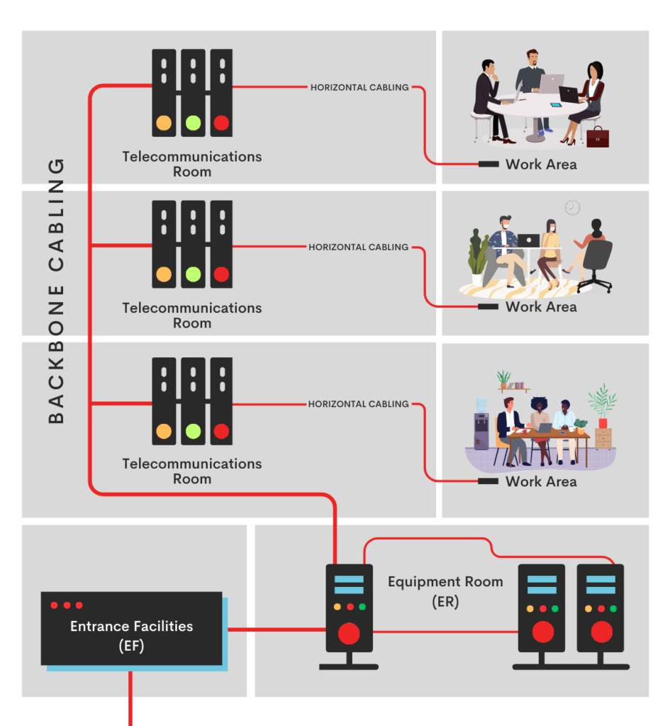
Backbone Cabling: Backbone cabling is a crucial component of structured cabling systems, providing the necessary connections between different areas of the network. It consists of two cabling subsystems that play a vital role in ensuring seamless communication and data transmission within the network.
Cabling Subsystem 2 serves as the link between horizontal cross-connects and intermediate cross-connects (IC). It is responsible for carrying the network traffic between these two points, ensuring that data flows smoothly and efficiently. This subsystem typically includes various options such as 100-ohm twisted-pair cables like Cat3, Cat5e, Cat6, and Cat6a, as well as multimode and single-mode optical fiber cables.
Cabling Subsystem 3 connects the intermediate cross-connects (ICs) to the main cross-connect (MC). The ICs act as distribution points within the network, allowing for the connection of multiple horizontal cabling subsystems. The main cross-connect (MC) serves as the central hub, linking all the ICs together and providing a centralized point for managing and monitoring the network.
When it comes to backbone cabling, organizations have various options to choose from. 100-ohm twisted-pair cables like Cat3, Cat5e, Cat6, and Cat6a are commonly used for shorter distances. These cables are cost-effective and provide reliable performance for data transmission within the network. For longer distances, multimode and single-mode optical fiber cables are recommended. Multimode optical fiber, with an 850 nm laser-optimized 50/125 μm configuration, is ideal for medium-range connections, while single-mode optical fiber is suitable for longer distances.
The choice of backbone cabling will depend on factors such as the network requirements, distance, bandwidth needs, and future scalability. It is essential to consider these factors during the planning and design phase to ensure optimal performance and compatibility with the network infrastructure.
Telecommunications Room (TR) and Enclosure (TE): These areas, whether as dedicated rooms or part of larger spaces, handle the termination of horizontal and backbone cables. They accommodate patch panels, jumpers, patch cords, and may include intermediate cross-connects (ICs) or main cross-connects (MCs) for expanded connectivity.
The Telecommunications Room (TR) and Enclosure (TE) are crucial components of the structured cabling system, providing a centralized location for terminating and managing the various cables within the network. Whether it is a dedicated room or a designated space within a larger area, the TR and TE play a vital role in ensuring the smooth operation of the network infrastructure.
One of the key functions of the TR and TE is the termination of both horizontal and backbone cables. Horizontal cables extend the telecommunications services to individual work areas, while backbone cables establish the connections between different areas of the network. By terminating these cables in the TR and TE, network administrators can easily access and manage the network connections, allowing for efficient troubleshooting and maintenance.
To facilitate the termination process, the TR and TE are equipped with essential components such as patch panels, jumpers, and patch cords. Patch panels provide the necessary ports for connecting and organizing the cables, allowing for easy identification and management of the network infrastructure. Jumpers and patch cords are used to establish the connections between the patch panels and the equipment or devices.
In addition to these components, the TR and TE may also include intermediate cross-connects (ICs) or main cross-connects (MCs) for expanded connectivity. ICs act as distribution points within the network, allowing for the connection of multiple horizontal cabling subsystems. They provide the necessary flexibility to accommodate the growing demands of the network. The MC, on the other hand, serves as the central hub that links all the ICs together, creating a centralized point for managing and monitoring the network.
The TR and TE not only provide a physical space for terminating and managing the cables but also contribute to the overall efficiency and reliability of the network. Proper organization and labeling of the cables within these areas make troubleshooting and maintenance tasks easier for network administrators. They can quickly identify and resolve connectivity issues, minimizing any potential disruptions to the network.
Horizontal Cabling (Cabling Subsystem 1): This subsystem extends telecommunications services to individual work areas, providing the necessary connectivity for end-user devices. It plays a crucial role in ensuring seamless communication within the network. With a maximum cable run of 295 feet from the Telecommunications Room (TR) or Enclosure (TE) to end-user devices, horizontal cabling is responsible for delivering reliable and efficient data transmission.
Horizontal cabling consists of various components that work together to establish the connections. Cables, connectors, patch panels, and jumpers are the key elements of this subsystem. They support a range of options, including Cat5e, Cat6, Cat6a cabling, as well as multimode and single-mode optical fiber. These options allow organizations to choose the most suitable solution based on their network requirements and performance needs.
Cat5e cables are commonly used for horizontal cabling due to their cost-effectiveness and reliable performance for data transmission within the network. They provide sufficient bandwidth for most applications and can support data rates of up to 1 gigabit per second (Gbps). Cat6 cables offer enhanced performance and higher bandwidth, making them suitable for more demanding applications. They can support data rates of up to 10 Gbps over short distances.
For organizations that require even higher bandwidth and performance, Cat6a cables are recommended. They are designed to support data rates of up to 10 Gbps over longer distances, making them ideal for future-proofing the network infrastructure. Additionally, multimode and single-mode optical fiber options are available for organizations that need to transmit data over longer distances or require greater bandwidth capacity.
Patch panels and jumpers play a crucial role in the organization and management of the horizontal cabling subsystem. Patch panels provide the necessary ports for terminating and organizing the cables, allowing for easy identification and maintenance. They serve as the central point for connecting the horizontal cables to the network equipment or devices.
Jumpers, on the other hand, establish the connections between the patch panels and the equipment or devices in the work area. They ensure that the data flows seamlessly from the horizontal cabling to the end-user devices, enabling efficient communication within the network. Proper organization and labeling of the cables within the patch panels and jumpers make troubleshooting and maintenance tasks easier for network administrators.
The horizontal cabling subsystem extends from the TR or TE to the work area, marking the endpoint of a structured cabling system. At the work area, cables are used to connect devices such as computers, phones, printers, and other network-enabled devices to the network. This ensures that end-users have access to the required telecommunications services and can effectively communicate and collaborate within the organization.
Work Area (WA): The WA encompasses the space from wall outlets to end-user devices, marking the endpoint of a structured cabling system. It includes the cable used to connect devices to the network.
The work area, also known as the end-user space, is where the structured cabling system directly interacts with the devices that people use on a daily basis. This space is where employees connect their computers, phones, printers, and other network-enabled devices to the network infrastructure.
The work area is a crucial part of the structured cabling system as it ensures that end-users have seamless access to the necessary telecommunications services. By providing a reliable and efficient connection, it enables employees to effectively communicate, collaborate, and perform their tasks within the organization.
Within the work area, wall outlets serve as the connection points between the devices and the cabling system. These outlets are strategically placed throughout the workspace to provide convenient access for employees. They are typically installed at a comfortable height and within reach, allowing for easy connectivity.
The cables used in the work area are specifically designed to connect devices to the network infrastructure. They come in various types, including Ethernet cables, telephone cables, and USB cables, to accommodate different device requirements. Ethernet cables, such as Cat5e, Cat6, and Cat6a, are commonly used for connecting computers and other network devices. Telephone cables, on the other hand, are used for connecting landline phones to the telephone network. USB cables are used for connecting devices like printers, scanners, and external hard drives to computers.
These cables ensure that data can flow seamlessly between the devices and the network infrastructure, enabling efficient communication and data transmission. They are typically terminated with connectors that match the specific device and network interface requirements, ensuring a secure and reliable connection.
In addition to cables, the work area may also include other components such as cable management solutions, power outlets, and surge protectors. Cable management solutions help keep the workspace organized by neatly organizing and securing the cables, preventing tangles and damage. Power outlets and surge protectors provide the necessary electrical power to the devices, ensuring they can function properly and safely
The work area serves as the final link in the structured cabling system, connecting the devices to the network infrastructure. It plays a vital role in ensuring that employees have access to the necessary telecommunications services and can carry out their work efficiently. By providing a reliable and efficient connection, the work area contributes to the overall productivity and success of the organization.
Benefits of Structured Cabling
Structured cabling offers several benefits for organizations of all sizes. These include:
Scalability: Structured cabling allows for easy expansion and modification of the network infrastructure. New devices and technologies can be added without the need for major rewiring or disruptions.
Flexibility: With structured cabling, organizations have the flexibility to support various network applications, such as data, voice, and video. This allows for the integration of different technologies and services.
Reliability: Structured cabling follows industry standards and best practices, ensuring a reliable and high-performance network infrastructure. It minimizes signal loss, interference, and downtime.
Easy Troubleshooting: The organized and labeled nature of structured cabling makes troubleshooting and maintenance tasks easier. Network administrators can quickly identify and resolve connectivity issues.
Cost-effectiveness: While the initial investment may be higher compared to other cabling options, structured cabling offers long-term cost savings. It reduces the need for frequent updates and repairs, and it can accommodate future technology upgrades.
By leveraging the benefits of structured cabling, organizations can establish a robust and efficient network infrastructure that supports their current and future needs.
Installation and Design Best Practices
To ensure the successful implementation of a structured cabling system, it is important to follow installation and design best practices. By carefully planning and considering various factors, organizations can optimize the performance and longevity of their structured cabling system.
The first step in implementing a structured cabling system is proper planning. Before installation, it is crucial to conduct a thorough assessment of the network requirements and layout. This involves determining the optimal cable routes, equipment locations, and connectivity needs. By carefully considering these factors, organizations can ensure that the cabling system is designed to meet their specific needs and provide the necessary connectivity throughout their network.
Another important aspect of implementing a structured cabling system is compliance with industry standards. Adhering to standards such as the TIA/EIA-568 and ISO/IEC 11801 ensures compatibility and performance. It is important to use certified cables, connectors, and equipment that meet these standards to guarantee the reliability and efficiency of the cabling system.
Proper cable pathways are essential for protecting and supporting the cables in a structured cabling system. Using appropriate cable pathways, such as conduits, cable trays, and raceways, helps to prevent damage to the cables and ensure their longevity. It is important to avoid tightly bending or overfilling the pathways, as this can cause signal loss or interference. By carefully selecting and installing the appropriate cable pathways, organizations can ensure the proper functioning of their cabling system.
Effective cable management techniques are also crucial in a structured cabling system. Implementing measures such as cable ties, racks, and labels helps to reduce cable clutter, prevent signal interference, and simplify future maintenance. Proper cable management not only ensures the neatness and organization of the cabling system but also facilitates troubleshooting and maintenance tasks. By investing time and effort into cable management, organizations can save valuable time and resources in the long run.
Thorough testing and documentation are vital steps in the implementation of a structured cabling system. After installation, it is important to thoroughly test the system to ensure proper functionality and performance. This involves verifying the connectivity, signal strength, and data transmission capabilities of the cabling system. Additionally, documenting the cable routes, connections, and labeling is essential for future reference and troubleshooting. Having detailed documentation allows network administrators to quickly identify and resolve any issues that may arise.
By following these installation and design best practices, organizations can optimize the performance and longevity of their structured cabling system. Proper planning, compliance with standards, appropriate cable pathways, effective cable management, and thorough testing and documentation are key factors in ensuring the successful implementation of a structured cabling system. By investing in a well-designed and properly installed cabling infrastructure, organizations can create a reliable and efficient network that can adapt to future technology advancements.
Why Is Structured Cabling Better Than Conventional Wiring?
Structured cabling is now the preferred networking infrastructure, offering significant improvements over traditional wiring systems. It enhances organization, scalability, performance, cost-efficiency, and is geared for future technological advancements.
This system is meticulously organized, using standardized components such as patch panels and horizontal cabling. This organization simplifies the management and maintenance of network infrastructure by eliminating the chaotic tangles typical of conventional wiring. As a result, structured cabling facilitates quicker troubleshooting, repairs, and overall network efficiency.
Another advantage of structured cabling is its inherent scalability and flexibility, which is essential for the growth of any business. Its modular setup allows for easy integration of new devices or modifications with minimal disruption. In contrast, traditional wiring systems often require extensive and costly reconfiguration, resulting in operational downtime.
From a performance standpoint, structured cabling offers reliable and high-speed connectivity that supports today’s demanding applications. It uses high-quality cables and components to minimize signal interference, ensuring fast data transfers and reduced latency. This contrasts sharply with the performance and reliability issues often associated with conventional wiring setups.
While the initial investment in structured cabling may be higher, it is cost-effective over the long term. The system’s efficient design reduces maintenance and operational costs, and its flexibility minimizes the expenses associated with network updates and reconfiguration. Moreover, its capacity to adapt to future technologies ensures that a business’s network infrastructure can evolve with the digital environment, preventing obsolescence. Investing in structured cabling is a strategic move for any business aiming to maintain a competitive edge in a rapidly advancing technological environment.
Future-proofing Your Network with Structured Cabling
One of the key advantages of structured cabling is its ability to future-proof the network infrastructure. With the rapid advancements in technology, organizations need a cabling system that can support emerging applications and higher bandwidth demands.
Structured cabling provides the flexibility to accommodate various network technologies, such as Gigabit Ethernet, 10 Gigabit Ethernet, and beyond. It can easily adapt to new data rates and protocols without the need for major infrastructure upgrades. This means that as technology continues to evolve, organizations can seamlessly integrate new devices and equipment into their network without the hassle of completely overhauling their cabling system. This not only saves time and resources but also allows for smooth transitions and minimal disruptions to the network.
Additionally, structured cabling allows for the seamless integration of wireless technologies, such as Wi-Fi access points and IoT devices. As the demand for wireless connectivity continues to grow, organizations can easily add and expand their wireless infrastructure without compromising the performance and reliability of their network. By incorporating wireless technologies into their structured cabling system, organizations can create a cohesive and unified network environment, where both wired and wireless devices can seamlessly communicate and interact.
Another aspect of future-proofing with structured cabling is its ability to support higher bandwidth demands. As technology advances, the need for faster and more efficient data transmission becomes increasingly important. Structured cabling is designed to handle higher data rates, allowing organizations to keep up with the increasing demand for bandwidth. This means that organizations can support bandwidth-intensive applications, such as video streaming, cloud computing, and virtual reality, without experiencing performance bottlenecks or network congestion.
By investing in structured cabling, organizations can future-proof their network and ensure that their infrastructure can support the evolving needs of their business. Whether it’s integrating new technologies, expanding wireless connectivity, or accommodating higher bandwidth demands, structured cabling provides the flexibility and scalability needed to adapt to future advancements. With a well-designed and properly installed cabling infrastructure, organizations can confidently embrace new technologies and stay ahead in today’s rapidly changing digital landscape.
In conclusion, structured cabling is a comprehensive and standardized approach to building a network infrastructure. It provides the foundation for efficient data, voice, and video transmission, and offers numerous benefits, such as scalability, flexibility, and reliability. By following installation and design best practices, organizations can optimize the performance and longevity of their structured cabling system. Furthermore, structured cabling allows for future-proofing, ensuring that the network infrastructure can support emerging technologies and higher bandwidth demands. With this comprehensive guide, you now have a solid understanding of structured cabling and its importance in creating a robust and efficient network infrastructure.
Common Structured Cabling Mistakes and How to Avoid Them
Structured cabling is a crucial part of modern network infrastructure, essential for reliable and scalable data transmission. However, if not properly installed and managed, it can cause significant issues. To ensure optimal performance and extend the lifespan of your network, it’s important to avoid common structured cabling mistakes.
One frequent mistake is inadequate planning and design, where organizations rush installation without fully considering their present and future network needs. This often leads to a disorganized system that struggles with scalability and adaptability. To prevent this, it’s vital to perform a detailed needs assessment and create a comprehensive cabling plan that considers future growth and equipment upgrades, tailored to your specific business requirements.
Another error is using low-quality materials and components to cut costs, which can result in poor performance and frequent system failures. These subpar materials are more susceptible to interference and physical damage, which can increase maintenance costs and cause network downtime. Investing in high-quality, industry-standard cabling and components is crucial, ensuring that all materials meet or exceed your network’s performance requirements.
Improper cable management can also undermine the efficiency and reliability of a structured cabling system. Tangled, poorly labeled, or incorrectly routed cables can lead to signal interference and complicate troubleshooting and maintenance. To avoid these issues, implement a rigorous cable management system with proper labeling, color-coding, and routing practices. Use organizers, trays, and ties to maintain a neat and orderly setup.
Neglecting to test and certify the cabling post-installation is another common oversight. Skipping this step can leave minor, yet impactful, installation errors undetected, affecting network performance. It’s essential to conduct thorough testing and certification to ensure the system functions correctly, including checks for continuity, signal strength, and adherence to industry standards.
Lastly, inadequate documentation and record-keeping can pose long-term management and maintenance challenges. Detailed records of the cabling layout, equipment connections, and any configuration changes are essential for efficient troubleshooting and future upgrades. Maintaining up-to-date, accessible documentation is crucial for anyone responsible for network maintenance.
By focusing on these key areas—careful planning, quality materials, proper management, rigorous testing, and thorough documentation—you can avoid common pitfalls in structured cabling. Doing so will not only reduce downtime and maintenance costs but also ensure a scalable, efficient network infrastructure ready to meet future demands.
I’m using the Ubuntu 16.04.3 droplet on DigitalOcean. In the examples below replace YOUR_FQDN with your FQDN; for this to work, it must have a valid hostname verifiable with a public DNS server.
Here’s my example A and CNAME entries on DigitalOcean:
Type  Hostname              Value
CNAME www.testunifi.foo.com testunifi.foo.com. (note the trailing '.')
A     testunifi.foo.com     107.xx.yy.zz
Enable the firewall and allow inbound ports
Ubuntu doesn’t start the firewall by default so enable that, and forward these ports. If you’re using a cloud provider with off-host network security, like AWS, remember to update the network configuration for these ports.
ufw enable
ufw allow ssh
# Allow 'informs'
ufw allow 8080/tcp
# Allow STUN
ufw allow 3478/udp
# Allow HTTP (forwarded to HTTPS) if you want the redirect
ufw allow 80/tcp
# Allow HTTPS
ufw allow 443/tcp
Install Unifi
Install the Unifi controller software if you don’t already have it.
The NGINX configuration can be tricky, and be sure to verify the settings with nginx -t -c /etc/nginx/nginc.conf. Execute systemctl reload nginx to reload the configuration.
Create the SSL certificates with certbot
certbot is a tool that reads the NGINX configuration and can easily renew certs and update NGINX configuration. Feel free to use letsencrypt directly if you’re needing a more custom approach.
Create the certificate using this, and you don’t need to forward 80 to 443 since the above configuration does that already. If certbot fails try restarting nginx or take the manual approach:
certbot --nginx
Reload NGINX and verify HTTPS sessions are valid
Reload nginx one more time, systemctl reload nginx, and try connecting to YOUR_FQDN on 80, which redirects to HTTPS.
Download the latest Win64-VS17 Apache version from www.apachelounge.com into your \Downloads\ folder. The packed file is named for instance httpd-2.4.55-win64-VS17.zip.
Unpack the downloaded ZIP archive in a folder with the same name, for instance httpd-2.4.55-win64-VS17.
Move all files inside the \httpd-2.4.55-win64-VS17\Apache24\ folder up one level. Then delete the (now empty) \Apache24\ folder.
Move the complete \httpd-2.4.55-win64-VS17\ folder to the \bin\apache\ folder of your Laragon installation.
In the Apache section, select the newly installed Apache version.
Laragon will restart the Apache Service using the new version.
Now you can remove the previous version by removing its folder from \bin\apache\.
In this lab we will install gns3 server not directly on linux host, but on a virtualized linux OS environment running inside an LXC container.
Usually hypervisors like VMware, VirtualBox, KVM,… virtualize machines running a guest OS, but they rely on the additional layer of the hypervisor to do that.
That’s not the case of LXC. It uses the underlying linux Kernel capabilities. An LXC container runs directly on the host OS.
This reminds me of type-1 native virtualization type.
The picture below illustrates the differences and the similarities between the traditional hypervisor-based virtualizationand container-based virtualization.
Often, the terms LXC and LXD are used interchangeably, but to be more accurate:
LXD is the CLI client application used to manage the containers.
LXC is the low level daemon used to access the kernel cgroups/namespaces capabilities.
Note:
LXC or LXC/LXD sometimes spelled individually “el ex see”, “el ex dee” or “lexy lexdy”
Differences and advantages of LXC over Docker containers:
The main difference between the two container technologies is that LXC containerizes an entire OS environement with independent file system where Docker is oriented to virtualize micro-services (single processes & applications).
For the other differences, here is a self-explanatory summary table:
After the first installation, we need to initialize LXC to set the storage and networking parameters:
sudo lxd init
Do you want to configure a new storage pool (yes/no) [default=yes]? no
Would you like LXD to be available over the network (yes/no) [default=no]? yes
Address to bind LXD to (not including port) [default=all]:
Port to bind LXD to [default=8443]:
Trust password for new clients:
Again:
Note:
If you are not prompted to configure lxc networking (bridge, ipv4, ipv6 addresses…), explicitly call the networking package configurator.
sudo dpkg-reconfigure -p medium lxd
Now, we need to install a remote image repository from which we will download the container OS image:
sudo lxc remote add rimages images.linuxcontainers.org
Generating a client certificate. This may take a minute...
If this is your first time using LXD, you should also run: sudo lxd init
To start your first container, try: lxc launch ubuntu:16.04
ping -c 5 10.230.44.115
PING 10.230.44.115 (10.230.44.115) 56(84) bytes of data.
64 bytes from 10.230.44.115: icmp_seq=1 ttl=64 time=0.080 ms
64 bytes from 10.230.44.115: icmp_seq=2 ttl=64 time=0.044 ms
64 bytes from 10.230.44.115: icmp_seq=3 ttl=64 time=0.043 ms
64 bytes from 10.230.44.115: icmp_seq=4 ttl=64 time=0.039 ms
64 bytes from 10.230.44.115: icmp_seq=5 ttl=64 time=0.036 ms

--- 10.230.44.115 ping statistics ---
5 packets transmitted, 5 received, 0% packet loss, time 4091ms
rtt min/avg/max/mdev = 0.036/0.048/0.080/0.017 ms
You can execute a command inside the container and exit right after:
sudo lxc exec gns3-server1 -- ip a
[sudo] password for ajn:
1: lo: <LOOPBACK,UP,LOWER_UP> mtu 65536 qdisc noqueue state UNKNOWN group default qlen 1000
    link/loopback 00:00:00:00:00:00 brd 00:00:00:00:00:00
    inet 127.0.0.1/8 scope host lo
       valid_lft forever preferred_lft forever
    inet6 ::1/128 scope host
       valid_lft forever preferred_lft forever
12: eth0@if13: <BROADCAST,MULTICAST,UP,LOWER_UP> mtu 1500 qdisc noqueue state UP group default qlen 1000
    link/ether 00:16:3e:21:4f:e0 brd ff:ff:ff:ff:ff:ff link-netnsid 0
    inet 10.230.44.115/24 brd 10.230.44.255 scope global eth0
       valid_lft forever preferred_lft forever
    inet6 fd1f:3af1:2cd0:c175:216:3eff:fe21:4fe0/64 scope global mngtmpaddr dynamic
       valid_lft 3148sec preferred_lft 3148sec
    inet6 fe80::216:3eff:fe21:4fe0/64 scope link
       valid_lft forever preferred_lft forever
Installing GNS3 server inside the LXC container:
To open a shell in the container:
sudo lxc exec gns3-server1 /bin/bash
Now you are inside the container environment
Let’s now check the connectivity with the outside world:
ping -c 5 google.fr
PING google.fr (216.58.219.227) 56(84) bytes of data.
64 bytes from lga25s41-in-f3.1e100.net (216.58.219.227): icmp_seq=1 ttl=56 time=2.08 ms
64 bytes from lga25s41-in-f3.1e100.net (216.58.219.227): icmp_seq=2 ttl=56 time=2.07 ms
64 bytes from lga25s41-in-f3.1e100.net (216.58.219.227): icmp_seq=3 ttl=56 time=2.06 ms
64 bytes from lga25s41-in-f3.1e100.net (216.58.219.227): icmp_seq=4 ttl=56 time=2.05 ms
64 bytes from lga25s41-in-f3.1e100.net (216.58.219.227): icmp_seq=5 ttl=56 time=2.03 ms

--- google.fr ping statistics ---
5 packets transmitted, 5 received, 0% packet loss, time 4005ms
rtt min/avg/max/mdev = 2.038/2.063/2.084/0.059 ms
Download the install script and install gns3 server without VPN option
docker login
Login with your Docker ID to push and pull images from Docker Hub. If you don't have a Docker ID, head over to https://hub.docker.com to create one.
Username: ajnouri
Password:
Login Succeeded
After the successful installation of GNS3 server, exit the lxc container
exit
On the server host, install OpenVPN package
apt-get install openvpn
Generate the static secret key
openvpn --genkey --secret secret.key
Start an OpenVPN server as deamon with the generated static key
172.16.253.1 and 172.16.253.2 are the tunnel private ip addresses in the server and client. They need to be mirrored on the client side.
192.168.0.0/24 is the private subnet on the client that need to be reachaed from the server.
Copy the static secret key to the client
scp secret.key ajn@X.X.143.38:/openvpn/secret.key
The authenticity of host 'X.X.143.38 (X.X.143.38)' can't be established.
ECDSA key fingerprint is SHA256:6H74AI6ei4yhhNNl7OuFxNcRtOq3Ha0KHSTaFsLffIw.
Are you sure you want to continue connecting (yes/no)? yes
Warning: Permanently added 'X.X.143.38' (ECDSA) to the list of known hosts.
ajn@X.X.143.38's password:


secret.key                                                                 100%  636     0.6KB/s   00:00
Client host configuration
In this case the client can be a baremetal or a traditional hypervisor-based VM on which OS and GNS3 GUI are installed.
Inside the client directory where the secret static key is copied, start openvpn session to the server
10.97.46.0/24 is the private subnet used by the LXC container on the server host.
Check the state of the OpenVPN session
sudo cat /tmp/openvpnclient.log
Fri Dec 29 14:39:10 2017 OpenVPN 2.3.4 x86_64-pc-linux-gnu [SSL (OpenSSL)] [LZO] [EPOLL] [PKCS11] [MH] [IPv6] built on Jun 26 2017
Fri Dec 29 14:39:10 2017 library versions: OpenSSL 1.0.1k 8 Jan 2015, LZO 2.08
Fri Dec 29 14:39:10 2017 TUN/TAP device tun0 opened
Fri Dec 29 14:39:10 2017 do_ifconfig, tt->ipv6=0, tt->did_ifconfig_ipv6_setup=0
Fri Dec 29 14:39:10 2017 /sbin/ip link set dev tun0 up mtu 1500
Fri Dec 29 14:39:10 2017 /sbin/ip addr add dev tun0 local 172.16.253.2 peer 172.16.253.1
Fri Dec 29 14:39:10 2017 UDPv4 link local (bound): [undef]
Fri Dec 29 14:39:10 2017 UDPv4 link remote: [AF_INET]X.X.72.185:1194
Fri Dec 29 14:39:20 2017 Peer Connection Initiated with [AF_INET]X.X.72.185:1194
Fri Dec 29 14:39:21 2017 Initialization Sequence Completed
Notice in the log file, the session with the server is established
From the client host, check the routing table for the subnet used by LXC container on the remote server.
ip r
default via 192.168.0.254 dev ovsbr0
10.20.20.0/24 dev vmnet1  proto kernel  scope link  src 10.20.20.1
10.97.46.0/24 via 172.16.253.1 dev tun0
Let’s ping the remote server lxc container IP where GNS3 server is installed:
$ ping 10.97.46.15
PING 10.97.46.15 (10.97.46.15) 56(84) bytes of data.
64 bytes from 10.97.46.15: icmp_seq=1 ttl=63 time=85.1 ms
64 bytes from 10.97.46.15: icmp_seq=2 ttl=63 time=84.8 ms
64 bytes from 10.97.46.15: icmp_seq=3 ttl=63 time=84.8 ms
64 bytes from 10.97.46.15: icmp_seq=4 ttl=63 time=84.5 ms
64 bytes from 10.97.46.15: icmp_seq=5 ttl=63 time=84.9 ms
^C

--- 10.97.46.15 ping statistics ---
5 packets transmitted, 5 received, 0% packet loss, time 4006ms
rtt min/avg/max/mdev = 84.566/84.866/85.114/0.318 ms
Bingo!
Now that the remote GNS3 server IP is reacheable from the client host, we need to configure GNS3 GUI with the server IP
The remote server should appear in the list of servers:
Caveat:
When trying to drop one of the installed container in the remote LXC server you might encouter this error:
I just had to try a couple of times for it to work.
Install and drop into the canvas a couple of containers and configure them with static IPs.
At its core, Laravel provides “guards” and “providers” to manage authentication. However, controllers, routes, and views still need to be implemented.
To achieve this, Laravel offers first-party packages that offer a complete authentication system, ready to use in just a few minutes. This is unique and the strength of Laravel: in no time, you can start developing your ideas.
However, multiple packages are related to authentication, and it can be challenging to know which one is adequate for your project.
Should you use Laravel Jetstream or Laravel Breeze? What are the differences between Laravel Passport and Laravel Sanctum? Is Laravel UI still an option?
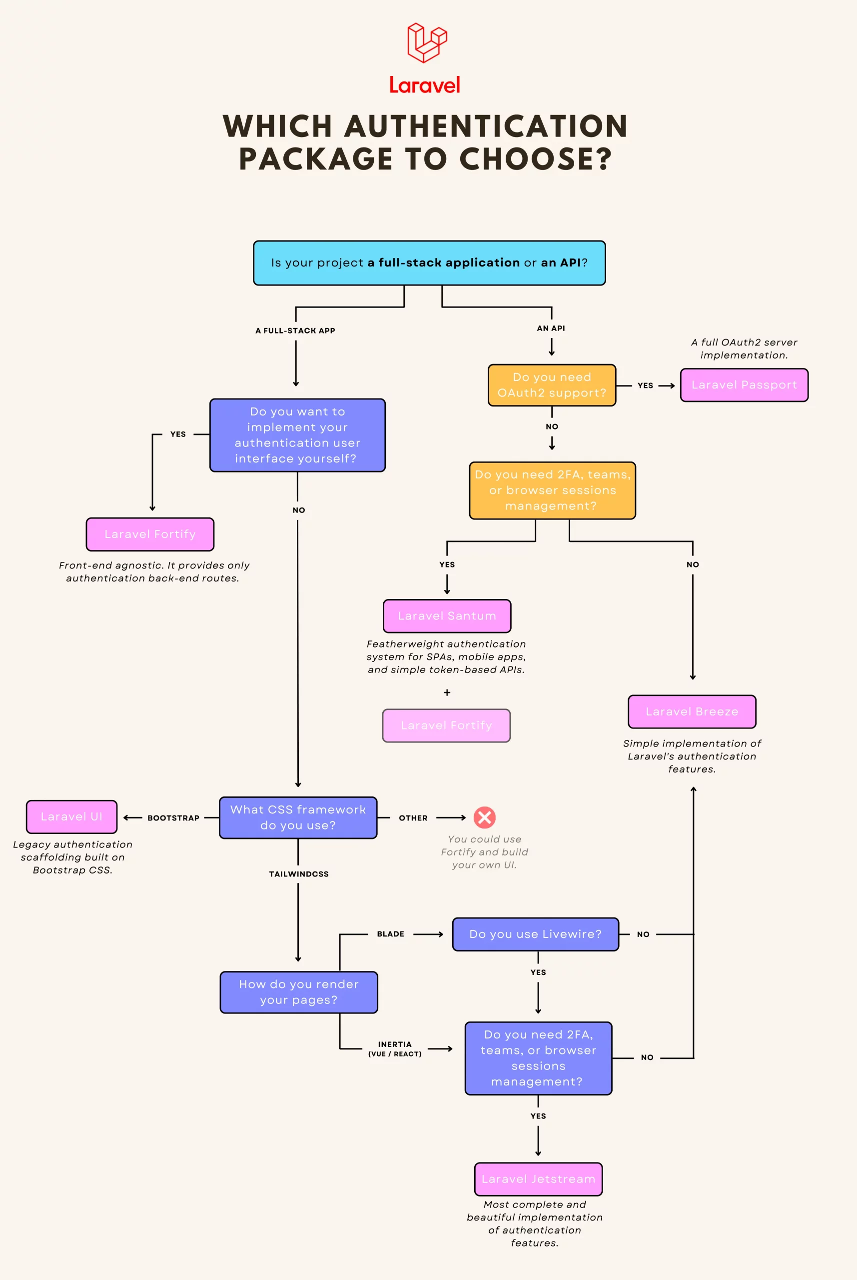
To help you find your way around, I have made a diagram to help you understand their differences and make the best choice for your project.
Which Laravel authentication package to install for your project?
Laravel Breeze
Breeze is a minimal and simple implementation of Laravel’s authentication features. It works both for full-stack applications and APIs. This is an excellent choice if you like simplicity or are brand new to Laravel.
You can choose between Blade, Vue/React (with Inertia), or API
It uses Tailwind CSS when Blade or Inertia stacks are chosen
✅ Registration
✅ Login
✅ Profile Management
✅ Password Reset
✅ Email Verification
Laravel Jetstream
More complete and stylish, Jetstream is an interesting alternative to Breeze. It provides more features but requires that your project uses Livewire or Inertia.
You can choose between Blade + Livewire or Vue/React + Inertia
It uses Tailwind CSS
✅ Registration
✅ Login
✅ Profile Management
✅ Password Reset
✅ Email Verification
✅ Two-Factor Authentication (2FA)
✅ Teams Management
✅ Browser Sessions Management (let users see where they’re logged-in)
✅ API Tokens & Permissions (let users generate API tokens)
Laravel Fortify
Fortify is a front-end agnostic implementation of all authentication features. It provides all routes and controllers needed to implement your authentication logic but requires you to code the user interface yourself. There are no views out of the box!
This is a great choice if you don’t use Tailwind CSS, want to code your front end yourself, or are building an API.
❌ No views, no user interface
✅ Registration
✅ Login
✅ Profile Management
✅ Password Reset
✅ Email Verification
✅ Two-Factor Authentication (2FA)
✅ Teams Management
✅ Browser Sessions Management (let users see where they’re connected and logout sessions)
✅ API Tokens & Permissions (let users generate API tokens)
For info, Jetstream uses Fortify under the hood and adds the UI layer.
Laravel UI
Laravel UI is the legacy scaffolding and brings a basic authentication system built on the Bootstrap CSS framework. Today, the only reason to install it is that your project uses Bootstrap CSS.
You can choose between simple HTML, Vue, or React
✅ Registration
✅ Login
✅ Password Reset
✅ Email Verification
Laravel Passport
Passport provides a full OAuth2 server implementation
Laravel Sanctum
Sanctum offers a simple way to authenticate SPAs or mobile applications that need to communicate with your Laravel-powered API. If you don’t need full OAuth2 support, this is a much simpler alternative to Passport.
✅ Middleware to authenticate your SPA (using cookie-based sessions)
✅ Middleware to authenticate clients using API tokens
✅ API tokens generation & permissions
❌ No authentication routes or controllers
Using Sanctum, you still have to implement your own authentication logic (creating your routes and controllers) or use it in combination with Fortify.
If you use it to authenticate a SPA, it needs to be hosted on the same root domain as your API since it uses cookie-based sessions.
I hope that all the authentication packages and starter kits of Laravel have no more secrets for you and that this article has made your choice easier if you were hesitating between them.
👋 I offer tech consulting services for companies that need help with their Laravel applications. I can assist with upgrades, refactoring, testing, new features, or building new apps. Feel free to contact me through LinkedIn, or you can find my email on my GitHub profile.
The wonderful world of Whois!, if you do not know what it is or what it is for, this is probably not the publication for you. But if you know what I’m talking about, then you’re going to be excited to know that you can stop using third-party services to check this information, with a little effort and love for programming you can create your own service! (I’m trying to add excitement to a query for information that, as necessary as it is, is quite common.)
Come on!, join me again to walk the yellow brick path… a path full of wonders!.
What is Whois?
Whois is a public service that allows you to check who owns a domain, its status, expiration dates, renewal and other information of interest.
You can use a Whois query to determine if a domain is available for purchase, for example. (Warning: Your mileage may vary, whois is generally quite reliable but can produce results you don’t expect), use it with caution.
Where can you find the Whois servers of a TLD?
IANA (the entity in charge of regulating the allocation of IP addresses and root DNS for address resolution) has a list at the following link:
Root Zone Database
The Root Zone Database represents the delegation details of top-level domains, including gTLDs such as .com, and… www.iana.org
This list will help us later to scrape and extract information necessary for our PHP Whois query script.
Warning: Scraping itself is not bad, but misused it ruins everyone’s party, always be very responsible and respectful regarding the information you grab using this technique.
Structure of our solution
Our directory and solution files will be as follows:
/whois           # root directory (your web server must have access to it)
  /cache         # This directory will store json files that contain the whois
                 # server address for a given TLD, these files will be used to catch
                 # the scraping process results.
  - index.html   # This file will be our entry point and GUI interface to query
                 # whois information.
  - getwhois.php # This script will receive the whois request from index.html
                 # and return the result.
  - Whois.php    # Our class definition with all attributes and methods used
                 # to query whois information.
Remember that you must have a web development environment with PHP or at least that you can execute php scripts through a command console. This time we will use PHP 8.2 on an Apache web server.
We will write our code based on three large blocks as follows:
Scraping
Whois request/query
Interface and result presentation
1. Scraping
Let’s do some scraping to extract the Whois server from each domain type (TLD) available in https://www.iana.org/domains/root/db. We will do it “on demand”, we will only scrape as necessary, that is, when we do not have a previous cache file for the TLD, this way we will reduce traffic, respect the site where the information comes from and reduce response times while querying.
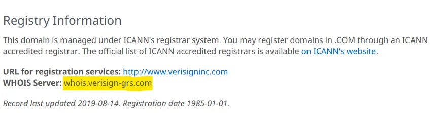
For example, we will visit the information of the TLD “.com”, the URL is https://www.iana.org/domains/root/db/com.html, general contact information will be shown and, at the bottom, the Whois server for this type of domains, like this:
iana.org whois
The address next to the text “WHOIS Server” will be the data of interest for our scrape process.
The first step will be to make a request to the website containing the required information and capture the HTML of the response. We can do this with our dear friend cURL like this:
    /**
     * This function downloads HTML content from a URL
     *
     * @param string $url URL to be queried
     *
     * @return string|bool HTML received in response from the website
     * if an error occurs it will return false
     */
    function curlDownload(string $url): string|bool
    {

        $curl = curl_init();

        curl_setopt($curl, CURLOPT_SSL_VERIFYHOST, 0);
        curl_setopt($curl, CURLOPT_SSL_VERIFYPEER, 0);
        curl_setopt($curl, CURLOPT_RETURNTRANSFER, true);
        curl_setopt($curl, CURLOPT_CONNECTTIMEOUT, 60);
        curl_setopt($curl, CURLOPT_HEADER, 0);
        curl_setopt($curl, CURLOPT_CUSTOMREQUEST, "GET");
        curl_setopt($curl, CURLOPT_USERAGENT, "Mozilla/5.0 (Macintosh; Intel Mac OS X 10_11_0) AppleWebKit/537.36 (KHTML, like Gecko) Chrome/74.0.3729.169 Safari/537.36");
        curl_setopt($curl, CURLOPT_URL, $url);

        $html = curl_exec($curl);
        curl_close($curl);

        return $html;
    }
In the User-Agent header, we set a value that simulates a visit from a desktop browser.
Now that we have got the content of the site, it is necessary to extract from the HTML received the address of the whois server, this can be done with a very useful tool, a tool that generates panic or immense hatred in the depths of the brave ones that dare to look it straight into its eyes, regular expressions.
No matter how you feel about it, always try to remember “Macho man” Randy Savage wise words:
You may not like it, but accept it! — “Macho Man” Randy Savage wisdom
We are going to review the content and create the regular expression, keep in mind that we are not going to cover in detail how it works, we will cover what is important, that it works for our present objective.
Let’s look at the source code of the page where the name of the whois server is located. The section we are interested in has this structure:
This expression looks for the text between the text pattern “<b>WHOIS Server:</b>” and the first match with the text “<p>”, using PHP we can capture the returned value and save it in a variable to use it later in our whois query.
Our sample code to understand this concept will look like this:
//Array that will be used to store the regex results.
$matchesWhois = array();

//Now we use our HTML download function created previously.
$html = curlDownload("https://www.iana.org/domains/root/db/com.html");
//Use the regex expression to extract the whois server from the HTML.
$resWhois = preg_match("#(?s)(?<=\<b\>WHOIS Server\:\<\/b\>)(.+?)(?=\<\/p\>)#", $html, $matchesWhois, PREG_OFFSET_CAPTURE);

//Now we remove the blank spaces from the result text, stored at the [0][0]
//element in the array
$matchesWhois[0][0] = trim($matchesWhois[0][0]);

//Finally assignt the whois server name to a variable.
$whoisServer = $matchesWhois[0][0];
2. Whois request/query
We already managed to query the name of the server to which we will request the whois information, now we need to implement the code to perform the query, for this we open a connection through sockets and send the domain name to receive a response with the whois data, like this:
//Open a connection to the whois server on port 43 with 20 seconds timeout limit.
$whoisSock = @fsockopen("whois.verisign-grs.com", 43, $errno, $errstr, 20);
//This variable will be used to store the whois result.
$whoisQueryResult = "";

//Send the domain name ending with new line.
fputs($whoisSock, "mytestdomain.com" . "\r\n");

$content = "";

//Read the server response.
while (!feof($whoisSock)) {
    $content .= fgets($whoisSock);
}

//Close the socket.
fclose($whoisSock);

//Convert the string to an array (one element for each line on the string)
$arrResponseLines = explode("\n", $content);

foreach ($arrResponseLines as $line) {

    $line = trim($line);

    //ignore if the line is empty or if it begins with "#" or "%"
    if (($line != '') && (!str_starts_with($line, '#')) && (!str_starts_with($line, '%'))) {
        //Append the line to the result variable.
        $whoisQueryResult .= $line . PHP_EOL;
    }
}

//Show the result.
echo $whoisQueryResult;
Now that we have the result, we will generate the code to query and display the result on the web.
3. Interface and result presentation
To query and show results we will create the Whois class that integrates the concepts previously shown, a file to receive query requests and the web interface to display the results.
Let’s start with our class, we will call it Whois.php and it has the following structure:
<?php

class Whois
{
    //Regex matches
    private array $matchesWhois;
    //Cache files path
    private string $_CACHE_PATH;
    //Regex used to detect the whois server while scraping the TLD URL
    private string $regexWhoisServer;
    //Cache files extension (.json)
    private string $_FILE_EXT;
    //Flag, True = using cache file, False = scraped result
    private bool $usingCache;
    //Domain name to being used to query the whois info.
    private string $domain;
    //Domain TLD
    private string $tld;
    //Cache file name
    private string $cacheFile;
    //URL used to scrape the whois server to be used.
    private string $urlWhoisDB;
    //Array that will contain the answer and errors generated during the whois query
    private array $response;
    //Array, contains the whois server address
    private array $whoisInfo;
    //Tag to be replaced by the domain TLD extracted from the domain name.
    private string $tldUrlTag;
    //Whois port, default 43
    private int $_WHOIS_PORT;
    //Whois query timeout in seconds, default 20
    private int $_WHOIS_TIMEOUT;
    //User Agent to be used to scrape the whois server info.
    private string $_CURL_USER_AGENT;


    /**
     * Class constructor
     */
    public function __construct()
    {
        $this->matchesWhois = array();
        $this->whoisInfo = array();
        $this->_CACHE_PATH = __DIR__ . "/cache/";
        $this->regexWhoisServer = '#(?s)(?<=\<b\>WHOIS Server\:\<\/b\>)(.+?)(?=\<\/p\>)#';
        $this->_FILE_EXT = ".json";
        $this->usingCache = false;
        $this->domain = "";
        $this->tld = "";
        $this->cacheFile = "";
        $this->tldUrlTag = "[TLD]";
        $this->urlWhoisDB = "https://www.iana.org/domains/root/db/{$this->tldUrlTag}.html";
        $this->response = array();
        $this->_WHOIS_PORT = 43;
        $this->_WHOIS_TIMEOUT = 20;
        $this->_CURL_USER_AGENT = "Mozilla/5.0 (Macintosh; Intel Mac OS X 10_11_0) AppleWebKit/537.36 (KHTML, like Gecko) Chrome/74.0.3729.169 Safari/537.36";
    }


    /**
     * Domain validation
     *
     * @param string $domain domain name to be validated i.e. "google.com"
     *
     * @return bool
     */
    public function isDomain(string $domain): bool
    {
        return filter_var($domain, FILTER_VALIDATE_DOMAIN);
    }


    /**
     * Extracts the TLD from the domain name
     *
     * @param mixed $domain domain name
     *
     * @return string
     */
    private function extractTld($domain): string
    {
        $arrDomain = explode(".", $domain);

        return end($arrDomain);
    }

    /**
     * Sets the cache filename for a given TLD, it also checks if the file exists and loads its content
     *
     * @param mixed $tld domain (TLD), i.e. "com", "net", "org".
     *
     * @return void
     */
    private function setCacheFileName($tld): void
    {
        $this->cacheFile = $this->_CACHE_PATH . $tld . $this->_FILE_EXT;

        if (file_exists($this->cacheFile)) {

            $tmpCache = file_get_contents($this->cacheFile);
            $this->whoisInfo = json_decode($tmpCache, true);

            $this->usingCache = true;
        }
    }

    /**
     * This function can be used to check if there where errors during the process
     *
     * @return bool true = there are errors, false = no errors
     */
    public function hasErrors(): bool
    {
        return isset($this->response["errors"]);
    }

    /**
     * Returns the response received including erros (if any).
     * @param bool $json Allows to select the response format, false = array, true = json
     *
     * @return array|string
     */
    public function getResponse(bool $json = false): array|string
    {
        return ($json) ? json_encode($this->response) : $this->response;
    }

    /**
     * This function downloads and returns the HTML returned from a URL
     *
     * @param string $url URL adddress
     *
     * @return string|bool string containing the HTML received, if there is an error return false.
     */
    private function curlDownload(string $url): string|bool
    {

        $curl = curl_init();

        curl_setopt($curl, CURLOPT_SSL_VERIFYHOST, 0);
        curl_setopt($curl, CURLOPT_SSL_VERIFYPEER, 0);
        curl_setopt($curl, CURLOPT_RETURNTRANSFER, true);
        curl_setopt($curl, CURLOPT_CONNECTTIMEOUT, 60);
        curl_setopt($curl, CURLOPT_HEADER, 0);
        curl_setopt($curl, CURLOPT_CUSTOMREQUEST, "GET");
        curl_setopt($curl, CURLOPT_USERAGENT, $this->_CURL_USER_AGENT);
        curl_setopt($curl, CURLOPT_URL, $url);

        $html = curl_exec($curl);
        curl_close($curl);

        return $html;
    }

    /**
     * Whois query entry point.
     *
     * @param string $domain domain name for which you want to check the whois
     *
     * @return void
     */
    public function getWhoisServerDetails(string $domain): void
    {

        $this->domain = $domain;
        $this->tld = $this->extractTld($domain);
        $this->setCacheFileName($this->tld);

        if (!$this->usingCache) {

            $urlWhoisDB = str_replace($this->tldUrlTag, $this->tld, $this->urlWhoisDB);
            $html = $this->curlDownload($urlWhoisDB);

            $resWhois = preg_match($this->regexWhoisServer, $html, $this->matchesWhois, PREG_OFFSET_CAPTURE);

            if ($resWhois != 1) {

                $this->response["errors"][] = array(
                    "error" => "TLD '{$this->tld}' not found!",
                    "domain" => $domain
                );

                return;
            }

            $this->matchesWhois[0][0] = trim($this->matchesWhois[0][0]);
            $this->whoisInfo["whois"] = $this->matchesWhois[0][0];

            file_put_contents($this->_CACHE_PATH . $this->tld . $this->_FILE_EXT, json_encode($this->whoisInfo, JSON_UNESCAPED_UNICODE));
        }

        if (!isset($this->whoisInfo["whois"])) {

            $this->response["errors"][] = array(
                "error" => "WhoIs Server for TLD {$this->tld} not found!.",
                "domain" => $domain
            );

            return;
        }

        $whoisSock = @fsockopen($this->whoisInfo["whois"], $this->_WHOIS_PORT, $errno, $errstr, $this->_WHOIS_TIMEOUT);
        $whoisQueryResult = "";

        if (!$whoisSock) {

            $this->response["errors"][] = array(
                "error" => "{$errstr} ({$errno})",
                "domain" => $domain
            );

            return;
        }

        fputs($whoisSock, $this->domain . "\r\n");

        $content = "";

        while (!feof($whoisSock)) {
            $content .= fgets($whoisSock);
        }

        fclose($whoisSock);

        if ((strpos(strtolower($content), "error") === false) && (strpos(strtolower($content), "not allocated") === false)) {

            $arrResponseLines = explode("\n", $content);

            foreach ($arrResponseLines as $line) {

                $line = trim($line);

                if (($line != '') && (!str_starts_with($line, '#')) && (!str_starts_with($line, '%'))) {
                    $whoisQueryResult .= $line . PHP_EOL;
                }
            }
        }

        $this->response["whoisinfo"] = $whoisQueryResult;
    }
}
In this class we will have all the main functions for scrape, whois server name extraction, domain name processing and final whois query. Note that error checking and handling routines were added, as well as functions to automate scraping from the domain type (TLD) queried and cache strategy to avoid making more queries than necessary to iana.org.
Now let’s create our file that will receive query requests, call it getwhois.php and it will have the following content:
<?php

//Include the class definition.
require("Whois.php");

//Decode the parameters received.
$paramsFetch = json_decode(
    file_get_contents("php://input"),
    true
);

//Create our whois object
$whoisObj = new Whois();
//Query the whois information
$whoisObj->getWhoisServerDetails($paramsFetch["domain"]);

//Return the response as JSON
echo $whoisObj->getResponse(true);
exit;
It is quite simple, it includes our Whois.php class, captures the parameters received from an HTML form that uses the javascript fetch function to send the request with the domain name, creates an instance of our class and makes the whois information query, then returns the result in JSON format and finishes the execution.
Now let’s go to the index.html file, this will be our graphical interface and the access point to the query and visualization of results. I use Bulma CSS for html controls an styling, it’s pretty straightforward, not intrusive, and you can generate results quickly. The file will look like this:
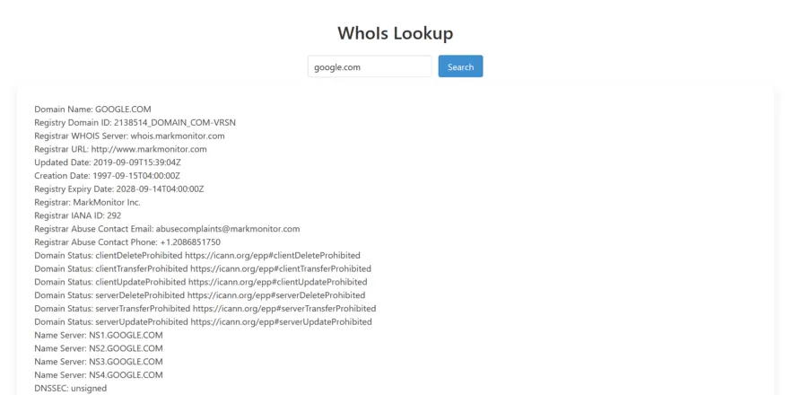
To perform tests it is only necessary point your browser to the path where our scripts are located, in my case http://localhost/whois, it will show the field to write the domain name and the “Search” button to request the Whois information. You can try a popular domain like “google.com”, the result will look like this:
After a successful whois query you will notice that in the /cache directory, a file will be created with the TLD, for example “com.json” and will contain the name of the corresponding whois server, this will allow us to avoid scraping again.
And that’s all, never forget that the one who is brave is really free, drink plenty of water, exercise and get enough sleep.
At Winkhosting.co we are much more than hosting. If you need shared hosting, domains or servers, stop by to visit us.